
What is a Toposolid and How Does It Work?
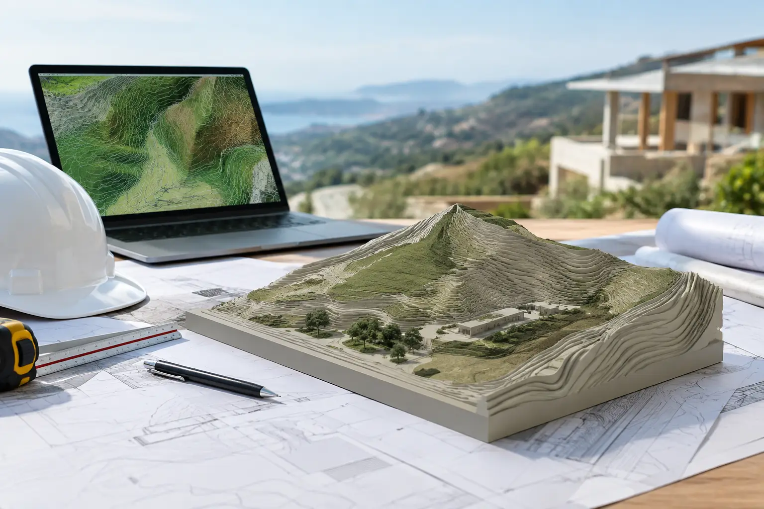
A building model can appear perfectly resolved until it is placed on an invented flat plane. So, what is a Toposolid? In Autodesk Revit, it is the native terrain element used to represent the existing or proposed ground as an editable, three-dimensional surface with thickness. It gives a site model physical form, allowing the terrain to interact more credibly with foundations, paths, retaining walls, planting areas and building levels.
For architects and BIM teams, the practical value is straightforward: a Toposolid turns elevation data into a model element that can be measured, sectioned, scheduled and coordinated. Its quality, however, depends almost entirely on the elevation points and coordinates used to create it.
What is a Toposolid in Revit?
A Toposolid is Revit's terrain modelling tool, introduced in Revit 2024 as the successor to the older Toposurface workflow. Like a floor, it has a defined thickness and can use layered materials. Unlike a floor, its upper face is shaped by elevation points, creating slopes, ridges, hollows and changes in level across a site.
This distinction matters. A Toposurface was primarily a triangulated skin: useful for showing ground, but limited when the model needed a more physical representation of soil, grass, gravel or sub-base. A Toposolid behaves more like a constructed model element. You can assign a type, control thickness, apply materials and cut or subdivide it with tools that better suit Revit's current modelling logic.
That does not mean a Toposolid is a replacement for civil engineering design software. It is highly effective for architectural site context, coordination and design development. Detailed earthworks calculations, road corridors, pipe networks and formal grading design may still require Civil 3D or specialist civil workflows. The right level of detail depends on the project stage and who owns the ground design.
Why the terrain element matters
Site levels affect far more than presentation. They determine whether a threshold is step-free, whether a ramp has enough run, where surface water moves, how much retaining structure may be required and whether a proposed finished floor level is plausible.
A Toposolid lets project teams see these relationships in the same environment as the building. Cut a section through an entrance and the ground profile is there. Check a boundary wall and you can identify a level difference before it becomes a late coordination issue. Test a landscape route and slopes can be reviewed against access requirements rather than guessed from a contour plan.
The model is only as trustworthy as its inputs. A terrain element built from sparse, unverified points can look convincing while missing a ditch, embankment, kerb line or local high point. For early massing, that may be sufficient. For drainage discussions, basement coordination or planning information, it may not be.
How a Toposolid is built
Revit creates the surface by triangulating elevation points. Each point has a horizontal position and a height, commonly expressed as X, Y and Z values. Revit joins those points into a network of triangular faces, then uses that network to form the top of the solid.
Point spacing controls useful detail
More points do not automatically produce a better model. Dense LiDAR-derived data can capture subtle terrain variation, but importing every available point can make a Revit file slow to open, edit and synchronise. Conversely, too few points can oversimplify a steep or irregular site.
Use point density that matches the task. A broad feasibility model may only need a restrained set of points that describes the principal falls. An entrance court, flood-sensitive edge or landscaped terrace may need closer spacing to retain meaningful local changes in level. It is often more effective to use a manageable site-wide dataset and add targeted points where design decisions need greater accuracy.
Boundaries and breaklines need judgement
The outer boundary defines the area Revit will model, but the boundary alone cannot explain abrupt changes in ground form. A retaining wall, channel, road edge or sharp crest may need carefully placed points or a separate modelling strategy to prevent the triangulation from smoothing across it.
This is where terrain modelling becomes a judgement call rather than a simple import operation. The aim is not to reproduce every surface imperfection. It is to preserve the ground features that affect design, coordination and communication.
A practical Toposolid workflow
The reliable workflow begins before Revit is opened. First, define the actual site extent required for the model. Include enough surrounding ground to understand approaches, adjacent levels and drainage direction, but avoid downloading an unnecessarily large area merely because it is available.
Next, obtain elevation data with known provenance and a clear coordinate reference system. Official national mapping, LiDAR and photogrammetry datasets can all be suitable, but their coverage, resolution and vertical accuracy differ. Check the data date as well. A site that has been regraded, developed or subject to earthworks may no longer match an older dataset.
Then clean and prepare the point data. Remove obvious outliers, retain a suitable spacing and make sure the file uses a consistent X, Y, Z structure. If the source is an XYZ or CSV file, confirm whether coordinates are in metres, feet, local grid values or a project-specific system. Do not assume the numbers are ready for Revit simply because they open in a spreadsheet.
In Revit, establish shared coordinates and confirm the relationship between the Survey Point, Project Base Point and the incoming terrain data. This is particularly important on projects where the building is modelled close to the internal origin but the real-world easting and northing values are large. A technically correct terrain model in the wrong location is still a coordination failure.
Create the Toposolid through the appropriate Revit command or an approved import workflow, then inspect it in plan, 3D and section. Review spot elevations at known locations, compare the model against survey information where available and look for triangulation artefacts. Finally, assign a suitable type and material so the ground reads correctly in views and sections.
For teams that need editable terrain data rather than a visual map surface, Topo-grapher is designed to generate site-boundary XYZ datasets that can be prepared for Revit Toposolid workflows. The useful output is not merely an image of a hillside. It is a coordinate-based point set that can be checked, simplified and brought into the project model with intent.
What a Toposolid can and cannot do
A Toposolid is well suited to existing-site representation, concept grading, landscape coordination, visibility studies, cut sections and early checks of access gradients. It can also help communicate the consequences of a design decision. Moving a building pad, for example, immediately changes how the structure meets the surrounding ground.
It should not be treated as proof that a site is buildable. A Toposolid does not replace a measured topographic survey, utilities investigation, geotechnical report or civil engineer's grading design. Publicly available elevation data is valuable for early design and many coordination tasks, but it has limits in resolution, date and vertical confidence.
Similarly, material layers do not make the model a full excavation specification. They can improve representation and quantities at an appropriate level, but construction take-offs need agreed rules, coordinated geometry and discipline-specific responsibility.
Toposolid versus Toposurface
If you work on legacy Revit projects, you may still encounter Toposurfaces. They remain relevant in older models, and migration should be planned rather than performed blindly. Views, hosted elements, subregions and existing site modelling methods may need review after conversion.
The central difference is that a Toposurface represents terrain as a surface, whereas a Toposolid represents terrain as a solid with depth. For new Revit workflows, Toposolids are generally the better starting point because they align with current versions of the platform and offer more useful material and modelling behaviour.
Coordinate discipline is the real test
The most common terrain problem is not the Toposolid tool. It is inconsistent coordinates. A model may be shifted because the data uses a different grid, scaled because metres and millimetres have been confused, or vertically wrong because heights refer to a different datum.
Before relying on the terrain, verify at least one known point, one site boundary location and the intended finished floor level. If the project requires consultant coordination, agree the coordinate convention early and document it. Correcting a terrain model at concept stage is quick. Discovering that it is displaced after links, drawings and landscape elements depend on it is not.
A well-built Toposolid gives the building a credible relationship with its site. Start with defensible elevation data, keep the point count proportionate to the decision being made, and check coordinates before the ground becomes embedded in the wider model.



