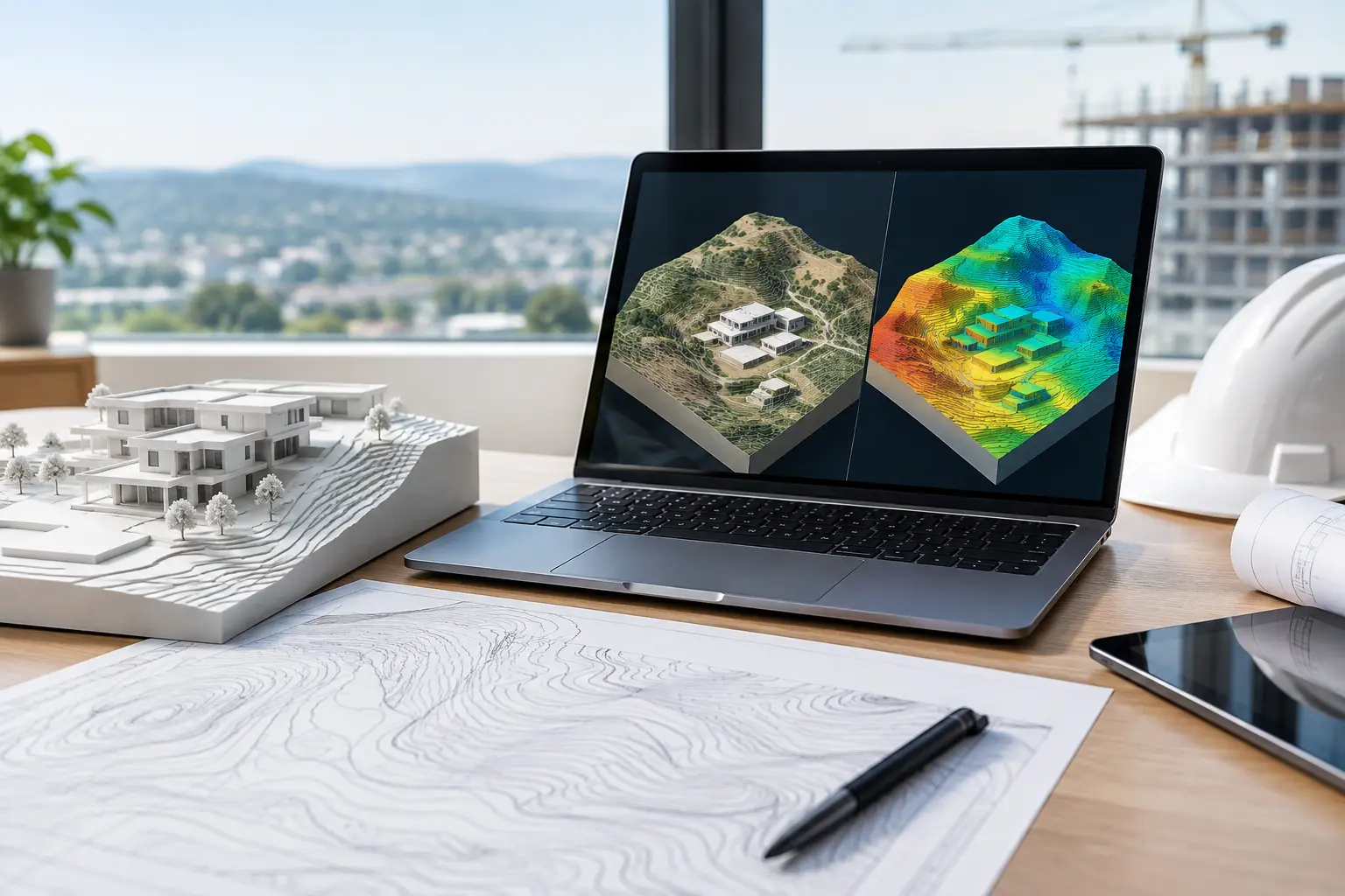
Masterplan Elevation Resolution: What Is Enough?

A 500-hectare masterplan can look convincing with a coarse terrain surface and still fail the first meaningful test: can the team identify where water moves, where streets meet existing ground, and where development parcels need cut or fill? Masterplan elevation resolution determines whether the model answers those questions or merely illustrates the site.
For early concept work, the goal is not to import every available LiDAR point. It is to select terrain data with enough horizontal detail, vertical confidence and coverage for the decisions being made. That balance matters particularly on large sites, where point density can quickly become a modelling-performance problem in Revit, Rhino, SketchUp or ArchiCAD.
What masterplan elevation resolution actually means
Elevation resolution is often treated as a single number, but it has two separate parts. Horizontal resolution describes the spacing between terrain samples across the ground. A dataset sampled at 1 m intervals captures more local variation than one sampled at 10 m intervals. Vertical resolution describes the smallest elevation increment the dataset records, while vertical accuracy indicates how close those reported heights are to the real ground.
These distinctions matter. A 1 m point grid may contain elevations recorded to centimetres, yet the actual vertical accuracy could be ±10 cm or more depending on the source, ground cover, survey method and processing. Conversely, a 5 m grid can be entirely appropriate for testing broad development zones on an expansive, relatively gentle site.
For a masterplan, resolution should be judged against the scale of the design decision. Regional movement corridors, broad landform and drainage catchments require a different terrain model from a detailed street interface, accessible route or retaining-wall study.
Start with the decision, not the densest dataset
A useful way to set a terrain brief is to identify the smallest ground feature that could change the proposal. On a large strategic site, this may be a swale, ridge, watercourse crossing or low point that affects the drainage strategy. On a sloping urban extension, it may be the level difference between a proposed street and existing plot boundaries.
If the model is only being used to establish development capacity, character areas and high-level road alignments, a moderate point spacing is normally sufficient. The surface needs to show the major terrain structure without loading the BIM model with millions of points that cannot improve the decision.
As the design reaches parcel planning, earthworks assumptions or blue-green infrastructure coordination, increase density within the areas under active study. This is usually more effective than generating a high-density model for the entire masterplan boundary. A large site can have one base terrain model for context and smaller, denser extracts for key junctions, drainage corridors, waterfront edges or steep zones.
Point spacing and site size must be planned together
Point count rises faster than most teams expect. Reducing point spacing from 10 m to 5 m does not double the number of points across the same area. It creates roughly four times as many samples. Reducing it again from 5 m to 1 m creates roughly 25 times as many points.
That has practical consequences for software performance. A terrain file that is reasonable in a GIS environment may become unnecessarily heavy when imported as a Revit Toposolid or converted into a dense SketchUp mesh. Slow orbiting, long regeneration times and unstable file sizes are not signs of a better site model.
For broad masterplanning, begin with a grid that represents the main landform cleanly. Check the resulting contours, sections and spot levels against the features that matter to the proposal. If a known ditch, embankment or local depression disappears, increase density only where necessary or use a separate detailed extract.
A sensible workflow is to maintain two levels of terrain information:
- A lightweight whole-site surface for massing, views, high-level movement and strategic grading.
- Focused high-resolution terrain areas for detailed coordination, access gradients, drainage routes and interfaces with existing infrastructure.
This approach also makes model ownership clearer. The central masterplan file remains usable by the wider team, while site, landscape and civil specialists can work with denser data where the geometry genuinely needs it.
Vertical accuracy matters more on shallow slopes
A vertical error of 100 mm may be insignificant on a steep hillside but critical across a nearly flat site. When ground falls at 1:200, a 100 mm difference in elevation can shift a theoretical drainage path by 20 m. That can change where attenuation is located, whether a street appears to drain, or how much level adjustment is needed to create a buildable platform.
Flat sites therefore need particular care. Do not assume that a visually smooth terrain model is reliable enough for drainage or finished-floor-level decisions. Review the source metadata, including stated vertical accuracy, survey date, coordinate reference system and whether elevations represent bare earth or surface features.
Vegetation is another common issue. Photogrammetry and lower-quality surface models can record tree canopy, buildings or hedges rather than the terrain below. For masterplanning, a digital terrain model derived from classified ground returns is generally more useful than a digital surface model. The difference can be substantial in wooded land, established parks and suburban sites with mature gardens.
Resolution cannot replace source quality
Interpolating a coarse elevation dataset into a denser mesh does not create new ground information. It simply creates more vertices between existing samples. The terrain may look smooth, but small features remain unknown.
The most dependable basis for design work is an official mapping, LiDAR or photogrammetric source with documented coverage and specification. Source quality should be assessed alongside resolution. Ask whether the data is current enough for a site that may have been regraded, developed or affected by new infrastructure since the survey date.
Coordinate handling is equally important. A terrain surface can be accurate in isolation and still cause errors if it is imported with the wrong horizontal or vertical reference. Confirm the coordinate system before export, retain real-world coordinates where the software workflow supports them, and establish how project coordinates will be shared between architectural, landscape and civil models.
Use contours and sections to check the result
Do not judge a terrain model only in perspective view. A shaded mesh can conceal poor sampling and misleading interpolation. Generate contours at an interval appropriate to the site, then cut sections across ridges, valleys, proposed streets and drainage lines.
Look for abrupt facets, flattened low points, unexpected terraces and contours that do not follow visible landform. These can indicate insufficient point density, unsuitable source data or a triangulation issue. Check spot elevations at known features where available, such as road levels, survey benchmarks or watercourse structures.
For a masterplan presentation model, it may be tempting to smooth the terrain aggressively. Keep the analytical model separate from any simplified visual model. Design decisions should be made from traceable elevation data, not from a surface altered solely for appearance.
A practical BIM workflow for large sites
Start by defining a boundary that includes more than the red-line site. Extend it far enough to understand incoming drainage, adjoining road levels, views and landform beyond the development edge. For a valley or hillside, the correct context extent may be much larger than the ownership boundary.
Generate the base terrain at a manageable spacing, then inspect point count before importing it into the authoring model. XYZ data is a practical exchange format because each point retains an easting, northing and elevation that can be checked, filtered and reused. Export a CSV where the software workflow requires it, or use IFC and DXF point data when coordinating with other tools.
In Revit, keep the whole-site Toposolid intentionally light and avoid using it as a detailed grading model. In Rhino and Grasshopper, separate source points from generated surfaces so density can be changed without rebuilding the entire definition. In SketchUp and ArchiCAD, test terrain complexity early because a visually acceptable mesh can still be expensive to edit.
Topo-grapher supports this workflow by producing editable XYZ terrain data from a user-defined site boundary, rather than a fixed web-viewer surface. The useful question remains the same: what resolution does this stage of the project need?
When to move beyond desktop elevation data
Public elevation data is highly effective for feasibility, masterplan options, early landscape strategy and coordination of broad site levels. It is not a substitute for a project-specific topographic survey when detailed design, contractual setting out, final drainage design or construction quantities are at stake.
Commission a survey when the proposal depends on tight tolerances, existing service covers, kerb lines, retaining structures, complex water edges or recently altered ground. The transition should be planned, not treated as a late correction. Set up the early model so the surveyed terrain can replace or validate the preliminary surface without breaking the project coordinate strategy.
The best masterplan terrain model is not the one with the smallest nominal point spacing. It is the one that reveals the ground conditions affecting the next decision, stays workable in the design software, and makes clear where further survey information is needed.