
Editable Terrain Data Comparison for BIM Teams
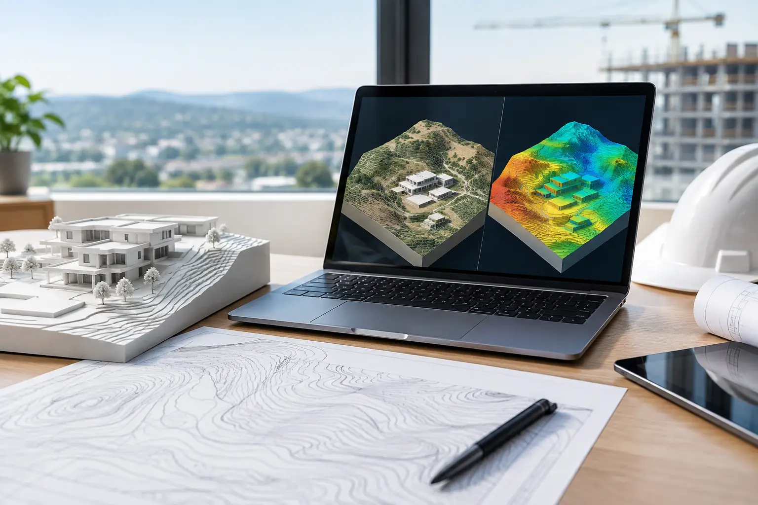
A terrain model can look convincing and still be unsuitable for design work. If the surface cannot be edited, does not retain real-world coordinates, or arrives as a heavy mesh with no usable elevation points, it will slow down every site decision that follows. An editable terrain data comparison should therefore start with the model’s practical purpose: setting finished floor levels, testing drainage falls, coordinating roads, or building a BIM context that other consultants can trust.
For architects and landscape teams, the useful question is not simply which terrain source looks best on screen. It is which source produces a manageable, traceable dataset that can enter Revit, SketchUp, ArchiCAD, Rhino or Grasshopper without a GIS clean-up exercise.
Editable terrain data comparison: what actually differs
Most terrain tools sit in one of three categories: visual map viewers, downloadable terrain meshes, and coordinate-based elevation datasets. They may all display hills, valleys and contours, but they behave very differently once a design team needs to alter the ground model.
A visual viewer is useful for early orientation. It can help a team understand whether a site rises towards the road or falls towards a watercourse. The limitation appears when the model needs to become part of a working file. Screenshot-based context and streamed web geometry cannot normally be interrogated, simplified or reshaped with confidence. It may also lack a stated vertical datum, source date or coordinate reference system.
A pre-built mesh is a step closer to a working terrain model. It can be imported into a modelling application and may be visually detailed. However, its triangles are often fixed, excessively dense, or disconnected from a clear set of XYZ points. Editing such a mesh can create awkward facets, inflate file sizes and make it difficult to explain where a level originated.
Coordinate-based elevation data is the most flexible option for BIM-led work. An XYZ file contains a list of points with easting, northing and elevation values. Those points can generate a Revit Toposolid, a SketchUp terrain mesh, an ArchiCAD Mesh, or a Rhino surface. The design team can filter points, add surveyed spot levels, reshape local areas and retain a direct relationship between the model and the source terrain.
That distinction matters because terrain is rarely left untouched. A building platform may require a cut and fill study. A landscape scheme may need accessible gradients. A planning model may need road levels checked against the proposed entrance. Editable data supports these tasks. A visual surface only illustrates them.
Compare the source before comparing the appearance
The first technical check is the source of the elevation values. Official national mapping, LiDAR and photogrammetry datasets each have a place, but they are not interchangeable.
LiDAR is often the preferred source where available because it captures dense ground information across large areas. Depending on the dataset and processing, it can provide useful detail for existing landform, embankments, ditches and broad drainage patterns. It is not automatically a substitute for a site survey. Vegetation, water, retaining walls and inaccessible areas can affect the derived ground surface, while project tolerances may exceed the dataset’s published vertical accuracy.
Photogrammetry-derived terrain can be valuable where LiDAR coverage is limited or where recent imagery provides better context. Its quality depends on image resolution, capture conditions and the processing used to distinguish ground from roofs, trees and other objects. It should be reviewed carefully on wooded or heavily developed sites.
National mapping data can provide dependable wider-area terrain coverage and is useful for feasibility studies, masterplanning and strategic massing. Its point spacing may be too broad for detailed landscape grading around a building, but that does not make it poor data. It simply means the model must be used at the correct scale.
Survey data remains the reference for decisions that carry contractual, construction or compliance consequences. When comparing editable terrain sources, treat open or national datasets as a fast and informed starting point, then integrate a topographic survey where design stage, risk and required accuracy demand it.
Point density is a modelling decision, not a quality contest
More points do not always create a better BIM terrain model. A dense cloud may represent subtle changes in landform, but it can also produce a slow Revit file, an uneven triangulated surface and unnecessary detail around a small building footprint.
The right spacing depends on the site and the decision being made. A broad rural masterplan can often use wider spacing because the model needs to communicate overall form and levels. A tight urban plot with retaining walls, access routes and threshold constraints needs more local detail. In either case, a team needs enough points to reflect meaningful grade changes without importing thousands of points that do not alter the design outcome.
This is where editable XYZ data has an advantage over a fixed terrain object. Teams can request or generate a practical site boundary, review the result, and reduce or refine density before building the final model. For Revit, keeping point counts proportionate to the site is particularly useful. A Toposolid does not improve simply because it contains every available point.
Use denser data where terrain changes rapidly, such as slopes, drainage channels, road edges or earthworks. Use a lighter sample over broad, consistent ground. If a critical kerb line, threshold or retaining wall affects the scheme, supplement the terrain dataset with surveyed levels rather than expecting a general elevation source to resolve it precisely.
Coordinate systems determine whether coordination works
A terrain model can be geometrically accurate and still fail coordination if its coordinates are handled incorrectly. Many modelling packages are sensitive to large real-world values, while project teams also need the model to align with survey control, civil files and georeferenced context.
Before importing, identify the horizontal coordinate reference system, the vertical datum and the units of the source data. Metres and feet are not a minor setting error when they affect site levels. Likewise, an elevation measured against one datum may not align with a survey tied to another.
A useful workflow is to retain the original XYZ data in its stated coordinate system, then establish a clear project approach for local modelling coordinates and shared coordinates. In Revit, this may mean setting up the project location and shared coordinate relationship before committing the terrain to a federated model. In Rhino or Grasshopper, it may mean moving geometry nearer the origin for stable modelling while preserving a documented transformation.
Do not flatten this issue by arbitrarily moving terrain until it looks correct beside a building model. Record the source, units, coordinate reference system and any transformation used. That small amount of discipline prevents later confusion when a civil engineer’s surface or a survey update arrives.
Exports determine whether data is genuinely editable
The format supplied is often the practical dividing line in an editable terrain data comparison. A rendered map tile is not an editable terrain file. Neither is a screenshot, and a generic 3D viewer export may create more work than it saves.
XYZ and CSV point files are broadly useful because they expose the geometry in a simple, inspectable form. Each row can be checked, filtered and supplemented. They are suitable inputs for terrain creation workflows across common design applications. DXF point exports can help teams that need CAD-compatible site information, while IFC may support coordination where the receiving workflow benefits from a structured exchange.
For a Revit workflow, import or link the point data through the Toposolid creation process, verify units, then inspect the resulting triangulation in section as well as plan. In SketchUp, use the points to generate terrain with an appropriate extension or workflow, rather than relying on an arbitrary textured surface. In Rhino, create a surface or mesh from the imported points, keeping the original point cloud available for checking and later revision.
The key test is simple: can the team add a proposed platform, revise a slope, replace a portion with survey data and export the result for coordination? If the answer is no, the terrain may be visually useful but it is not a productive design input.
A practical selection method
Choose terrain data according to the next decision the project needs to make. For an initial feasibility study, official elevation data with moderate point spacing may be enough to establish massing, access and broad drainage direction. For a landscape concept, increase detail around paths, terraces and water movement. For technical design, combine editable terrain with current survey information and consultant coordination.
Topo-grapher is designed for this point in the workflow: define the site boundary, generate real-world-coordinate terrain data and download a clean XYZ file for the modelling environment already in use. The benefit is not a more decorative site model. It is reducing the gap between a location on a map and a terrain dataset that can support real design actions.
The best terrain file is rarely the densest or most photorealistic one. It is the one your team can understand, edit and coordinate without losing track of where the levels came from.



