
Terrain Software for BIM Site Models
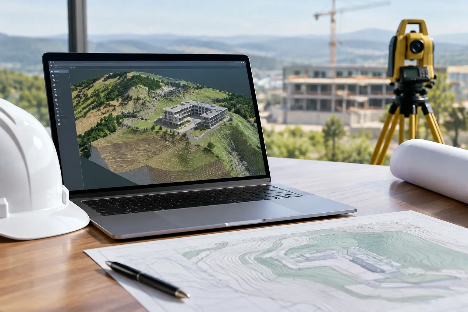
A terrain model can look convincing and still be unusable for design. Terrain software becomes valuable when it produces editable elevation data in real-world coordinates, at a point density your BIM or modelling application can handle. That difference determines whether a site model helps with levels, drainage and coordination, or simply provides a background surface for early visuals.
For architects and landscape teams, the goal is not to become GIS specialists. It is to move from a project address or defined boundary to dependable XYZ points that can be imported, checked and developed in the same environment as the building model.
What terrain software should actually deliver
Many web mapping tools provide shaded relief, aerial imagery or a navigable 3D view. These are useful for understanding a place, but they do not necessarily provide a terrain dataset that can support model-based decisions. A screenshot has no usable elevation values. A web mesh may be visually detailed but lack a stated coordinate reference system, survey date, vertical accuracy or export route.
Usable terrain software starts with a defined site extent. You should be able to draw a polygon or rectangle, enter coordinates, or search for a location. The boundary matters because it controls both the relevant area and the eventual point count. Generating a city-scale surface for a single building plot creates a heavy model without improving decisions at the site edge.
The output should be an editable file, usually XYZ or CSV, with each row representing an easting, northing and elevation. That is the practical bridge into Revit Toposolids, Rhino point workflows, Grasshopper definitions, SketchUp terrain meshes and Archicad Mesh tools. It also gives the project team a dataset they can inspect rather than a black-box object.
Data provenance matters as much as file format. Elevation points sourced from official national mapping, LiDAR or photogrammetry datasets can be assessed against their stated coverage and resolution. The best available source varies by location. Dense urban areas, wooded land, steep coastlines and recently altered sites all require a more careful reading of what the source represents.
Select the site boundary before selecting point density
The most common terrain-model problem is not bad elevation data. It is an undefined modelling purpose. Before generating anything, decide what the terrain must answer.
For early massing, a boundary extending beyond the plot may be enough to show the approach road, adjacent ground and broad landform. For a planning view, include the visible context that affects building height, retaining walls or access. For drainage studies, external works or civil coordination, draw around the actual flow paths and interfaces rather than relying on a neat property outline.
Point spacing should follow that purpose. Wider spacing creates a lighter file and is often appropriate for a large masterplan or early feasibility model. Closer spacing captures more local variation, but it can make BIM files slow and difficult to edit. Revit, in particular, benefits from a controlled number of points. A dense LiDAR-derived dataset may be excellent source information, yet still need thinning before it becomes a practical Toposolid.
This is a trade-off, not a rule that more points are always better. If the design decision concerns a broad 1:1000 site slope, very dense points add little. If the project includes a ramp, terrace, swale or retaining strategy, the team may need a smaller generation area with tighter spacing around that feature. Treat the generated terrain as a purposeful model input, not a complete digital twin of the ground.
A practical terrain software workflow
A reliable process can be kept short when the terrain service handles source retrieval and export preparation.
1. Define a coordinate-aware area
Locate the project, then draw the boundary around the land that affects the design. Check that the selected extent includes road levels, site access and relevant neighbouring ground. For sloping sites, include enough upslope and downslope context to understand how water and level changes move through the proposal.
If the model will be shared with surveyors, engineers or a wider consultant team, record the coordinate system and units at this stage. Coordinate mistakes are far cheaper to correct before import than after a building, landscape and civil model have each been developed independently.
2. Generate points for the modelling task
Choose a sensible point spacing and confirm the expected point count. A compact architectural plot can generally use finer sampling than a large campus or infrastructure corridor. Keep separate exports where necessary: one lightweight context surface for everyday BIM work and one denser local dataset for detailed landscape or parametric analysis.
Topo-grapher follows this workflow by converting a selected boundary into clean XYZ terrain data, so teams can start with a file intended for modelling rather than a visual terrain viewer. Where source coverage permits, the output retains real-world coordinates that can support later coordination.
3. Inspect the data before building a surface
Open the CSV or XYZ file in a spreadsheet or text editor and verify the structure. Confirm that the first two values are horizontal coordinates and the third is elevation, that decimal separators are interpreted correctly, and that units match the intended project setup. A quick inspection can expose a swapped axis, a header row that an importer will misread, or an unexpectedly large coordinate range.
Also check for features that should not be mistaken for bare ground. Depending on the source, elevation data may reflect vegetation, roofs, bridges or other objects. A road crossing beneath a bridge, for example, cannot be reliably inferred from a general surface alone. Existing survey information and civil data remain necessary when the design moves towards construction-level set-out.
4. Import using the application’s native terrain workflow
In Revit, import or create the terrain through the Toposolid workflow, ensuring the project’s shared coordinates and elevation units have been established first. Review the resulting surface in section, not only in perspective. A site that appears acceptable in a 3D view can reveal stepped contours, an incorrect datum or an offset building level as soon as a section is cut.
In Rhino, import the XYZ points and create a surface or mesh appropriate to the intended operation. Grasshopper users can retain the points as a source dataset, then control interpolation, smoothing and contour generation explicitly. This is useful where the terrain must feed graded platforms, sightline studies or rule-based drainage logic.
SketchUp and Archicad users should follow the same principle: create an editable terrain object from the point data, then preserve the original export separately. Do not rely on a triangulated result as the only record of the source elevations. You may need to regenerate the terrain at a different density after the design scope changes.
Check terrain against project levels, not just contours
A terrain surface should immediately be tested against known project information. Compare it with benchmark data, spot levels, road levels, survey drawings or measured site photographs where available. The aim is not to demand survey-grade certainty from every public dataset. It is to understand whether the model is fit for the current decision.
Start with simple checks. Does the ground fall in the expected direction? Do key road edges sit plausibly relative to the proposed finished floor level? Is the building pad above, below or cutting through the imported surface? Are contours behaving sensibly at the site boundary?
Then assess the risk. For concept design, an authoritative broad terrain dataset may be entirely suitable for placing the building, testing access and identifying likely cut-and-fill implications. For drainage detailing, retaining-wall foundations or construction quantities, supplement it with a current site survey and the engineer’s design levels. Terrain software reduces the time to an informed model. It does not remove the need for professional verification where tolerance and liability increase.
Avoid the three shortcuts that create bad site models
The first shortcut is modelling from imagery alone. Aerial photos are excellent context, but shadows and perspective do not provide reliable height information. The second is importing every available point at maximum density. This produces slow files, obscures modelling intent and makes revisions harder. The third is manually moving the terrain until it looks right beside the building. That may solve a visual problem while breaking coordinates for every later exchange.
Instead, keep the source export, document the coordinate reference and datum, and make deliberate edits as design work rather than accidental adjustments. If you create proposed grading, distinguish it clearly from existing terrain. Existing ground is evidence; proposed ground is a design decision.
The most useful terrain model is rarely the most detailed one. It is the one that gives the team a credible answer to the next site question, remains light enough to work with, and can be traced back to a coordinate-aware source when the project needs to go further.



