
Terrain Boundary Extraction for BIM Site Models
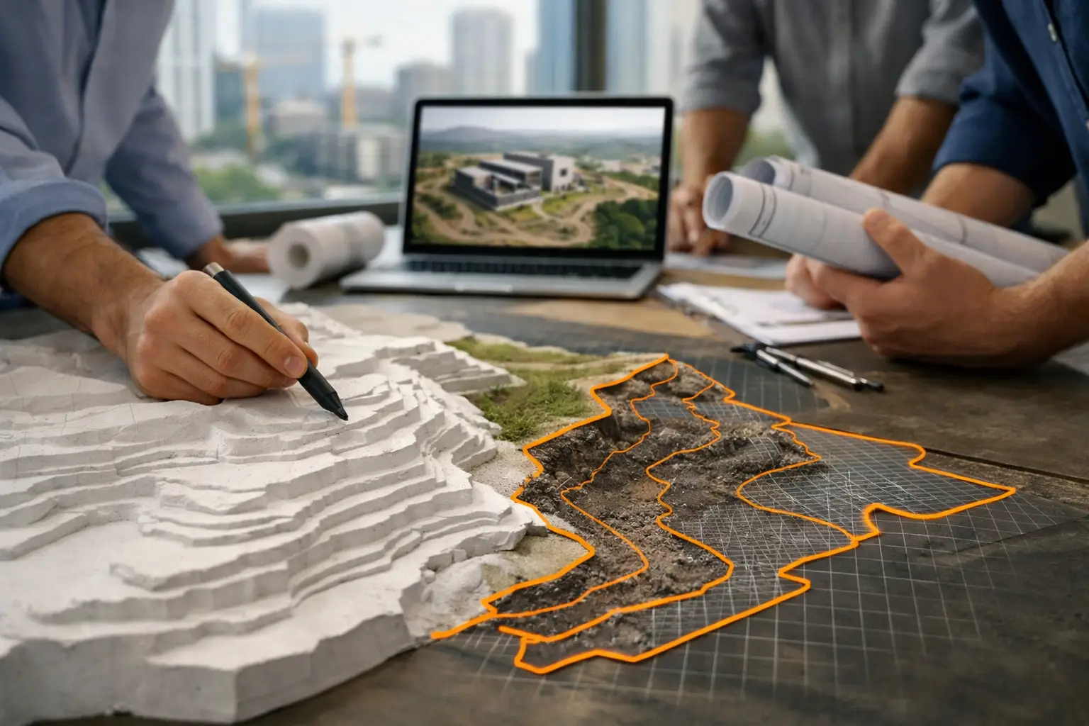
A terrain model is only as useful as the boundary used to create it. Draw too wide and Revit slows under unnecessary points. Draw too tight and the model misses the road crown, neighbouring levels, drainage route or retaining condition that explains how the site actually works. Terrain boundary extraction is the practical step that turns a project extent into a usable elevation dataset rather than a generic patch of landscape.
For architects and BIM teams, the aim is not to collect the largest possible area of terrain. It is to define the right area, retrieve defensible source elevations, and export a point cloud that remains editable in the modelling software where decisions are made.
What terrain boundary extraction actually does
Terrain boundary extraction selects elevation data within a defined polygon, rectangle or coordinate extent. The boundary tells the data service which part of the underlying mapping, LiDAR or photogrammetry dataset to retrieve. The result should be a set of XYZ points in known real-world coordinates, ready to become a Toposolid, Mesh, surface or terrain model.
This is different from tracing contours from a map image or downloading a visual terrain object from a web viewer. An image can help with context, but it does not provide editable surveyed coordinates. A visual mesh may look convincing from a distance, yet still be unsuitable for setting finished floor levels, testing accessible gradients or coordinating with civil information.
A properly extracted boundary gives the project team control over three things: the area being modelled, the density of points being imported, and the coordinate reference of the output. Those controls determine whether the terrain is a working design input or just presentation geometry.
Start with the design question, not the property line
The legal site boundary is often a poor terrain boundary. Terrain responds to slopes, water paths, street levels and adjacent land, none of which stop neatly at a red-line edge.
For a small extension on a level suburban plot, an extraction area that includes the house, garden and immediate pavement may be enough. For a hillside dwelling, include land uphill and downhill of the proposed building so the model reveals the approach gradients and likely surface-water movement. A landscape scheme may need the full park edge, nearby paths and outfall direction. A masterplan requires a wider context, but it also needs sensible point management to keep the BIM model workable.
Before drawing anything, identify the decisions the terrain must support. These commonly include building placement, cut-and-fill studies, accessible routes, retaining walls, drainage falls, road tie-ins and views. The required extent follows from those decisions.
Add a context buffer
As a working rule, extend the extraction beyond the immediate intervention area until the surrounding levels are clear. The correct buffer depends on slope and project scale. Flat urban sites may only need a modest margin. Steep sites, rural plots and projects near embankments, watercourses or roads generally need more.
The buffer is not wasted data when it captures the controlling condition. A road level 30 metres beyond the plot may matter more to a proposed entrance than hundreds of points inside a flat garden.
A practical terrain boundary extraction workflow
The most efficient workflow keeps boundary definition, data generation and software import as separate, deliberate tasks.
1. Locate the site accurately
Search for the address or place the project using coordinates. Check that the base map aligns with known features such as roads, building footprints, parcel edges and watercourses. If the project is being coordinated to a survey grid, establish that requirement before exporting any terrain.
A location name alone can be ambiguous, particularly on large rural sites or developments with new postal addresses. Coordinates reduce that risk and give the team a repeatable reference for later checks.
2. Draw an extent that follows the terrain problem
Use a rectangle for simple, regular sites where quick coverage is more useful than a tightly controlled point count. Use a polygon where a corridor, irregular parcel or constrained site makes a rectangle inefficient.
Do not create a highly detailed polygon simply because the boundary tool allows it. Every unnecessary bend takes time to verify and does not improve the terrain. The goal is a clear operational extent, not a legal drawing.
Where a scheme has separate areas of interest, such as a building plot and a remote drainage connection, it can be better to generate separate terrain datasets. This keeps each model focused and prevents one oversized export from becoming difficult to handle.
3. Check source coverage and resolution
Elevation quality depends on the available source data. Official national mapping, LiDAR and photogrammetry datasets differ by country, collection date, point spacing, vegetation treatment and vertical accuracy. A dense dataset can represent ground form well, but it should not be treated as a substitute for a site survey where construction tolerances, legal boundaries or critical levels are at stake.
For early-stage massing, feasibility and option testing, authoritative public elevation data can provide a strong basis for decisions. For detailed grading, setting-out or coordination with existing utilities, confirm the project requirements with the surveyor and civil engineer.
This distinction matters around trees, dense vegetation and complex built edges. Some datasets classify ground effectively; others may include artefacts from vegetation, structures or retaining walls. Review the generated terrain against known site conditions before relying on it.
4. Set point density for the receiving software
More points do not automatically produce a better BIM model. They can create slow file performance, heavy regenerations and a surface that is difficult to edit. Revit in particular benefits from a considered point count. A terrain surface should show meaningful breaks in slope without reproducing every minor variation contained in the raw dataset.
Use a coarser spacing for broad site context and an appropriate finer spacing around grading-sensitive zones. For a typical building plot, the right density is the one that preserves road falls, terraces, banks and drainage routes while leaving the model responsive. If the extracted area is large, generate a lighter context model first and reserve denser data for the working design zone.
5. Export XYZ data with coordinate discipline
XYZ data should retain a clear horizontal and vertical reference. If the model will sit alongside survey information, civil files or an IFC coordination model, coordinate consistency matters as much as terrain shape.
A CSV or XYZ file is often the most direct route into design software because each row contains an easting, northing and elevation value. It is transparent, easy to inspect and broadly compatible. Where required, DXF point files, IFC output, site maps and building data can support parallel coordination tasks.
Keep the original export unchanged. If you create a decimated or edited version for a particular model, name it clearly with the site, date, coordinate system and point spacing. That simple discipline prevents a common problem: teams comparing terrain models that appear similar but were generated from different extents or resolutions.
Bringing the extracted terrain into your model
In Revit, import the prepared CSV or XYZ data when creating a Toposolid, then verify units, orientation and shared coordinates before placing the proposed building. Check a few known spot levels against the source information. A surface that looks correct in perspective can still be vertically offset.
In SketchUp, the same point data can support terrain mesh workflows, though practical mesh performance should guide the number of imported points. In Rhino and Grasshopper, XYZ values can be used to construct a surface, filter points by elevation or distance, and test design geometry against the existing ground. Archicad users can use the data to build a Mesh with project-appropriate reference levels.
The modelling command is only the final step. The value comes from arriving there with clean points, a deliberate boundary and coordinates that can be understood by everyone on the project.
Common mistakes that create misleading site models
The first is extracting only the building footprint. This produces a terrain object but removes the surrounding levels needed to understand access, drainage and transitions to existing ground.
The second is importing a city-scale extent at full density into a building model. The extra data rarely improves a design decision and often makes the file harder to use. Split the site, reduce the point count or create different terrain models for context and detailed design.
The third is treating public elevation data as construction survey information. Source terrain is highly useful, but its resolution, age and classification should match the design stage and risk level. Verify critical levels independently.
The fourth is losing track of coordinate systems. A model shifted from its expected location may still look visually acceptable in isolation, then fail when linked to survey, structures or services. Record the reference system at generation and carry it through the workflow.
Good terrain boundary extraction is a small action with a direct effect on every site decision that follows. Define the extent around the real design problem, keep the dataset proportionate to the model, and preserve coordinates from export to coordination. The result is terrain that stays useful when the project moves from an early option to a conversation about actual levels, falls and buildability.



