
Rhino NURBS Terrain from Points Made Practical
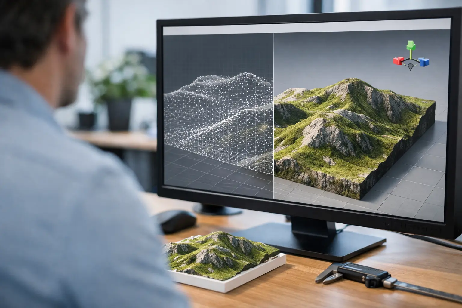
A Rhino NURBS terrain from points is useful when the site model needs to do more than look convincing in a rendering. It needs to carry dependable spot levels, support section studies, inform drainage decisions and sit in the same coordinate logic as the wider project. The quality of the final surface depends less on a single Rhino command than on the point data, the way it is prepared and how closely the surface is allowed to follow it.
For early massing, a coarse terrain may be enough. For a landscape scheme, cut-and-fill study or coordination with civil information, the surface needs a more controlled workflow. Start with clean XYZ data, then choose a NURBS method that matches the distribution and density of the source points.
That's where Topo-grapher.com comes in, try it out for free
Start with a usable XYZ point set
A NURBS surface cannot correct poor elevation data. Before importing anything into Rhino, confirm what each column represents, which units it uses and whether the points are in a known coordinate reference system. A typical terrain file contains three values per row: X, Y and Z. The horizontal coordinates establish position; Z is the elevation.
Keep the data limited to the area the model actually needs. A large regional dataset may contain tens of thousands of points that add little value to a building-scale study, while making the Rhino file slow and the resulting surface difficult to edit. Include enough context beyond the design boundary to understand surrounding falls, overland flow and connections to adjacent streets, but avoid importing a whole district by default.
Point spacing should reflect the decisions being made. Five-metre spacing can be appropriate for broad masterplanning and conceptual site context. One- or two-metre spacing may be needed around a small site where swales, retaining edges and accessible gradients matter. Greater density is not automatically better: a dense LiDAR-derived set can capture vegetation, kerbs, walls and other objects unless it has been classified or filtered as ground data.
Topo-grapher is designed for this step: define the site area, generate terrain from authoritative elevation sources and download an editable XYZ file rather than a visual terrain tile. Before bringing the file into Rhino, open it in a spreadsheet or plain-text editor and check for headers, blank rows, duplicate coordinates and unexpected text values.
Prepare Rhino before importing points
Set the Rhino model units before importing. If the file is in metres, work in metres. A unit mismatch can turn a 12-metre contour interval into an unusable 12-millimetre site model, and it is much easier to prevent than repair.
Coordinate magnitude matters as well. Survey and mapping coordinates can be very large because they reference a national or local grid. Rhino can display such geometry, but modelling, snapping and surface operations are generally more reliable near the world origin. For most design workflows, retain the real-world coordinate information externally or in a dedicated reference layer, then move the imported terrain points close to 0,0,0 for modelling.
Record the translation exactly. If the project later needs to return to survey coordinates, that offset is part of the deliverable, not a temporary convenience. Use named layers to separate imported source points, working points, the generated terrain surface and any proposed grading geometry. Lock the original point layer once the import has been checked.
Import and inspect the points in Rhino
Use Rhino's point-file import workflow to read the XYZ file, selecting the correct delimiter and confirming that the columns map to X, Y and Z. Depending on the file format and Rhino version, this may be handled through Rhino as such: Rhino imports a point file through File > Import (or the _Import command). It reads .csv, .txt and .xyz, and asks you to map the columns and set the delimiter. The important check is visual: the imported objects must be Rhino point objects positioned at the correct scale and elevation.
Switch to a perspective view, then inspect the points from the side. A plan view can hide a vertical error completely. Use the Distance command to test several known elevations, and compare the overall minimum and maximum Z values with the source file. If a site expected to rise by 8 metres appears flat, investigate units, decimal separators and column mapping before creating any surface.
Remove obvious outliers before surface generation. A single high point from a tree canopy, building roof or bad return can pull a NURBS patch into an artificial spike. Do not delete points merely because they create an inconvenient slope, however. Check them against survey information, contours, imagery and neighbouring levels first. The objective is a defensible ground model, not a smoother-looking one.
Create the Rhino NURBS terrain from points
For irregularly distributed terrain points, the Patch command is normally the most practical starting point. Select the validated points and run Patch. Rhino creates an interpolated or approximated NURBS surface across the point field, with controls for surface stiffness, U and V spans, trim behaviour and sampling.
Treat those settings as modelling decisions. A surface with too few spans will smooth over real landform and can miss a meaningful ridge or low point. One with too many spans may chase minor noise in the source data, producing ripples that complicate contours, sections and downstream fabrication. Begin with a restrained span count, inspect the result, then increase complexity only where the site geometry justifies it.
Stiffness controls how freely the patch responds to the selected points. A stiffer surface gives broad, calm transitions, which can suit preliminary studies based on low-resolution mapping. A less stiff surface follows local variation more closely, which can be appropriate for clean, dense ground points. Neither setting makes uncertain data more accurate.
Use a boundary curve if the surface should be limited to a defined site area, but avoid trimming directly at the outermost points. Patch requires enough surrounding information to establish a credible edge condition. Extending the source area beyond the project boundary and trimming the finished surface back usually produces a more stable result.
When Surface from Points is the better command
Surface from Points is appropriate only where points form a consistent rectangular grid with known row and column order. It is common in controlled computational workflows, but most imported survey, LiDAR and terrain XYZ files are scattered rather than structured. Applying it to unordered points creates a distorted surface or fails altogether.
If the data is a regular grid, count the points and confirm the grid dimensions before running the command. In Grasshopper, the equivalent workflow also requires correctly ordered data branches. This is a data-structure problem, not a surface-quality setting.
Validate the surface before using it
A surface can look plausible and still be unsuitable for design decisions. First, turn on the original points and inspect whether they sit consistently on or near the NURBS terrain. Use PointDeviation or ClosestPoint checks at representative locations to understand the difference between the source points and the generated surface.
Then use Contour to create intervals that suit the project scale, such as 0.25 m or 0.5 m for a detailed landscape study. Contours reveal unwanted waves quickly. Review long sections through the site, particularly across proposed entrances, drainage routes, terraces and building platforms. A visual perspective alone is not enough for checking falls.
Keep existing terrain separate from proposed terrain. The existing NURBS surface should remain a traceable representation of source data. Build proposed pads, ramps, retaining transitions and grading surfaces independently, then compare them through sections, Boolean operations or Grasshopper analysis. This separation makes design changes easier to understand and prevents a conceptual grading move from overwriting the surveyed context.
Know when a NURBS surface is not the right terrain model
NURBS terrain is excellent for smooth ground, conceptual landform and Rhino-based coordination. It is less suitable where sharp breaklines are critical, such as kerb edges, retaining walls, channel inverts or engineered road crowns. A patch can soften these features because it has no inherent understanding of a breakline.
In those cases, use explicit curves and separate surfaces, or create a controlled terrain mesh that honours breaklines. Meshes also tend to be lighter for very large datasets and can be preferable for visualisation, analysis or exchange. The right choice depends on whether the next task is surface editing, grading, rendering, fabrication or civil coordination.
A reliable terrain model is not the one with the most points or the highest surface degree. It is the one whose source, units, coordinate handling and tolerances are clear enough that the team can trust every level they take from it.



