
How to Extract Terrain from Site Polygons
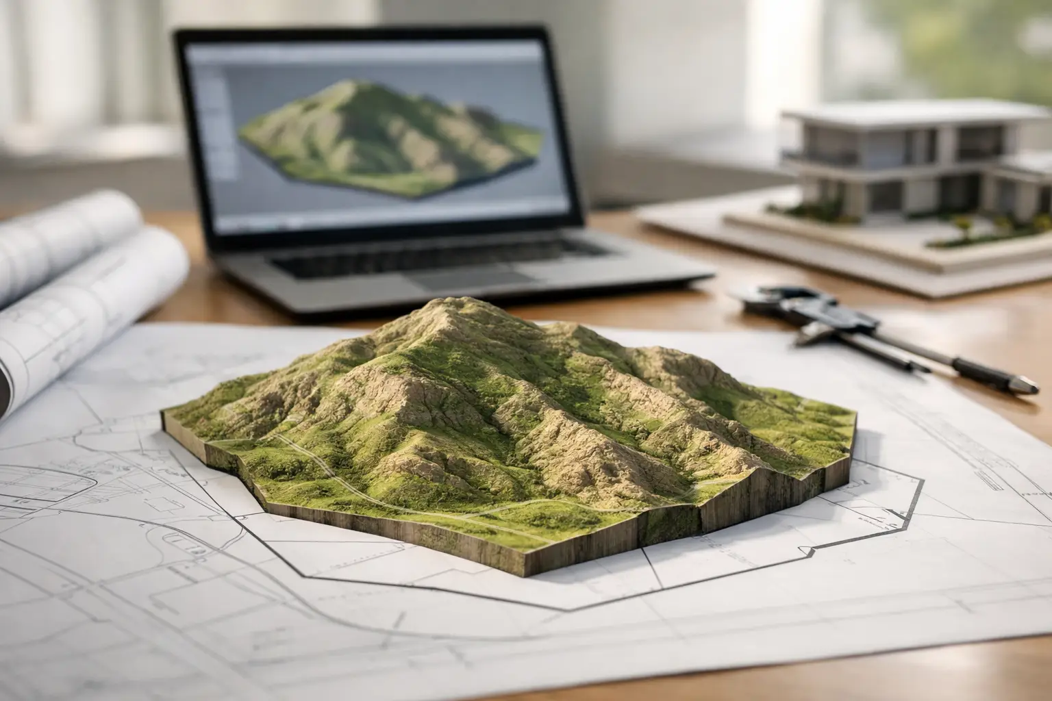
The site polygon is a modelling decision, not an administrative outline. Draw it too tightly and you lose the access road and drainage path that explain how the plot actually behaves. Draw it too broadly and you sit waiting while Revit tries to build a Toposolid from 40,000 points you never needed.
The useful outcome is editable terrain in real-world coordinates. Not a shaded satellite image, not a screenshot dressed up as a site model. Something you can turn into a Toposolid, mesh, or NURBS surface and then check against your levels, pads, drainage falls, and access grades.
This is a working guide to getting that terrain, from a mapped boundary to a Toposolid, Sandbox mesh, Rhino patch, or ArchiCAD Mesh, without touching Civil 3D or QGIS.
Why extract terrain from a site polygon
A polygon gives the request a spatial limit. Instead of downloading a national LiDAR tile and clipping it in GIS, you tell the map where the site is and only that data comes back. The output covers the area you drew, in the coordinate system you asked for, ready to import.
That matters more than it sounds. On a small housing plot a 0.5m fall changes finished floor level, retaining allowance, and threshold detail. On a masterplan the catchment upstream of the site controls surface water, road tie-ins, and visible ridgelines. The polygon should follow the question being asked, not the title deed.
Government open data (LiDAR, photogrammetry, and national DEMs) will beat any visual terrain viewer once you have it in a modelling format. But it is not a survey. Ground cover, vegetation returns, capture date, and point classification all vary. Use it for feasibility, option testing, planning-stage models, and contextual coordination. Verify critical construction levels against a proper topographic survey before you build off them.
Set the boundary before you touch resolution
Start with the polygon. Search the site, paste coordinates, or draw the boundary directly on the map. Then look at it honestly: does this area answer the design question this week, or is it just the legal outline?
A few starting points from real projects:
- Small building plot. Push the polygon 5 to 15m past the proposed footprint on every side so you catch the pavement, boundary treatment, and the immediate fall of the land.
- Sloping site. Extend uphill and downhill until you can see where water arrives and where it leaves. Chasing runoff off the page is worse than a slightly larger extract.
- Streetscape or infill. Include the opposite kerb line. Threshold heights and pavement crossfalls on the far side often control your entrance detail.
- Masterplan or landscape scheme. Model the wider catchment where ridgelines, visibility, and drainage matter. You can trim later, but you cannot invent data you did not download.
Resolution comes second. Tighter point spacing represents local variation more closely, especially with 0.4m Danish DHM or 0.5m SRSP Scottish LiDAR under the hood. It also makes the file heavier, which matters when the terrain has to live inside a central Revit model that fifteen other people are working in.
There is no universal setting. As a rough starting frame:
- Feasibility, massing, contextual model: wider spacing, lighter file, fast to display.
- Grading, drainage, retaining detail: tighter spacing around the elements that need it.
- Landscape and hardscape studies: dense enough to see swales and paths, sparse enough to edit.
Keep the resolution proportionate to the decision. A 5,000 point Toposolid you can actually manipulate is more useful than a 60,000 point surface everyone is afraid to touch.
Step-by-step: from polygon to editable terrain
1. Draw the boundary that supports the decision
Draw the polygon and then look at it again with the design question in mind. Building orientation and general slope needs less area than a drainage assessment. Do not trace every kink of the legal boundary unless that precision changes the terrain outcome.
2. Generate the elevation data
Generate from the boundary and pick the export format that matches your target application. What matters technically is: a known horizontal CRS, reliable elevations against a documented vertical datum, and a format that preserves both through export. In practice most BIM and modelling workflows want one of three things:
- XYZ CSV for direct point import into Revit, ArchiCAD, or a Rhino/Grasshopper workflow.
- DXF for a ready-to-use 3D mesh in SketchUp, Rhino, or AutoCAD.
- IFC for a linked terrain element that behaves like a model reference.
This is where a browser-based extractor removes the GIS bottleneck. Topo-grapher converts a mapped polygon into any of those formats without you sourcing tiles, clipping rasters, or converting coordinate systems by hand. It pulls from national LiDAR and photogrammetry sources: 0.4m in Denmark, 0.5m in the Netherlands and parts of Scotland, 1m across England, Sweden, Canada, and much of the US 3DEP coverage, and a 30m global fallback where nothing better exists.
3. Sanity-check the file before you import it
Open the CSV and look at it before Revit does. Confirm:
- Column order (X,Y,Z or E,N,Z, matching what your app expects).
- Units (metres or survey feet, consistent through the export).
- Decimal separator (comma-versus-period bites people who move files between locales).
- Coordinate reference (national grid, UTM zone, or local project grid).
A terrain that opens thousands of metres from your project origin is not wrong, just inconvenient. The fix is a shared-coordinate or local-origin workflow, not editing the elevations. If you change the Z values to make it look right in the viewport, you have quietly broken every level check downstream.
4. Build the terrain in your target application
The command differs per application, but the principle stays the same: preserve source coordinates, document any transformation, and keep existing terrain separate from proposed grading.
Revit (Toposolid)
Since Revit 2024 the Toposolid replaced the old Toposurface. Import via Massing & Site → Toposolid → Create from Import → Create from Points File, select the CSV, and confirm units.
Two things worth knowing before you generate a very dense CSV:
- Revit 2024 and 2025 automatically downsample point-file imports to 10,000 points. So if you throw a 60,000 point CSV at it, Revit picks 10,000 for you, which may not be the 10,000 you wanted. Better to generate at the density you actually need.
- Revit 2026 lets you raise that ceiling by editing `Revit.ini` (up to around 50,000), but performance still degrades quickly on large sites once you go past 15 to 20 thousand points.
Also worth flagging: Building Pads are gone as of Revit 2024. If you were using pads to punch the building footprint into the topography, you now do that with voids or grading regions on the Toposolid itself. The Toposolid behaves more like a floor than the old Toposurface, so it is heavier to edit but plays better with hosted elements. Set phasing to Existing on the imported terrain and use Graded Region for proposed grading if you want cut and fill volumes to schedule correctly.
Longer walkthrough: XYZ CSV to Toposolid.
SketchUp
SketchUp Pro has no native XYZ point importer. You have two clean routes:
- DXF mesh. Export the terrain as DXF and use File → Import. The terrain arrives as 3D faces you can group and start modelling against. This is the fastest path in SketchUp Pro and works with any recent version.
- Contours through Sandbox. Export contour lines as DWG, import, explode, select the contours, and use Sandbox → From Contours. Save first. Sandbox can be resource-hungry on dense data.
Raw XYZ points into SketchUp really needs a plugin such as Fredo6's TopoShaper. If you have the choice, the DXF mesh route avoids the extension and gives cleaner geometry. Full walkthrough: SketchUp terrain import.
Rhino and Grasshopper
Import the CSV as points, then decide what you want the terrain to be:
- NURBS surface, use `Patch`. It fits a smooth surface through the points and will not intersect every one exactly. Good for visualisation and downstream NURBS operations, less good if you care about exact elevations at every sampled point.
- Mesh, use `MeshPatch`, or Delaunay triangulation in Grasshopper. The mesh honours the sampled points, which is usually what you want for existing terrain.
Grasshopper users can hold the points as an input and drive contours, cut-and-fill comparisons, view studies, or parametric placement rules from there.
ArchiCAD
The exact command is File → Interoperability → Place Mesh from Surveyors Data. Point it at the XYZ or TXT file, set the unit, pick placement, and confirm sea level. It builds a native Mesh element you can then edit with the Mesh tool, add ridges, adjust points, or split for landscape treatment.
If your survey came in as DWG rather than XYZ, ArchiCAD can still handle it, but the mesh-from-surveyors route is faster and less error-prone than tracing contours by hand.
Check the model before you issue it
A terrain can look believable and still be wrong. Before it goes in the coordination model, check a handful of known or visually obvious locations:
- Road and kerb levels along the frontage.
- Ridge lines and any high points you can eyeball on aerial imagery.
- Drainage channels and low points.
- Building threshold conditions where the design assumes a specific level.
- The polygon corners, which sometimes show interpolation artefacts on the edges.
Sudden spikes usually mean vegetation returns that were not filtered out, source noise, or an import problem with your delimiter or decimal separator. Flat plateaus in an otherwise varied site can mean sparse data, or that the source is a DSM (first return, tops of trees and roofs) rather than a DTM (bare earth). Most national LiDAR products publish both. For architectural use you almost always want the DTM.
While you are checking, confirm the vertical datum. Elevations may come referenced to a national datum, ODN in Great Britain, NAVD88 in the US, DVR90 in Denmark, DHHN in Germany, ISN2004 or ISN2016 in Iceland. Your consultant survey may reference a different one. A consistent offset across the whole site is not a graphics glitch if it is silently offsetting your floor levels and utility falls.
For coordination hygiene, name the file clearly (Existing Terrain, source, date, spacing), and record it somewhere the civil engineer will actually see it. That gives the team enough to judge whether it is fit for concept, planning, or an initial civil check.
Common mistakes that produce poor terrain models
Treating the polygon as a legal boundary. The title outline may exclude the road that controls access levels, or include a field that adds nothing to the design conversation. The polygon is a modelling decision, not a legal exercise.
Assuming denser is always better. Dense data has its place, especially for landscape and drainage detail. It also increases file size, import time, and editing overhead, and makes source noise look more important than it is. Start with what the current stage needs, regenerate a denser extract only where the design demands it.
Confusing existing terrain with grading design. The extract describes the surface at capture date. Pads, falls, retaining edges, and proposed contours are design decisions. Keep them in a separate Toposolid, mesh, or graded region, and always with a clear existing-versus-proposed phase.
Ignoring the vertical datum. Terrain that is 1.8m off across the whole model is the kind of mistake that only shows up in a coordination review or, worse, on site. If your survey is on a project datum and your extract is on a national one, do the offset deliberately and write it down.
A repeatable site workflow
Done well, terrain generation stops being a specialist detour and becomes a repeatable project task. Draw the boundary that answers the current question, pick a sensible density, keep coordinate and datum discipline, and export only the data your model can actually use. The result is a terrain base that gets the team making site decisions early, and leaves the critical levels ready for a proper survey and civil review when they matter.
Generate your site terrain free →
Frequently asked questions
What file format should I use for site terrain?
XYZ CSV for direct point import into Revit, ArchiCAD, and Grasshopper. DXF for a ready-to-use mesh in SketchUp or Rhino. IFC for a linked terrain element in a coordinated BIM model. All three carry real-world coordinates, so the choice comes down to what your target application prefers to eat.
How dense should the point spacing be?
Match it to the decision. Feasibility and massing usually work at 5 to 15m spacing. Grading, drainage, and landscape studies want 1 to 3m in the areas that matter. Going tighter than the source resolution does not add real detail, it just interpolates existing values into more points.
Why does my Revit Toposolid only show part of the data?
Revit 2024 and 2025 downsample point-file imports to 10,000 points automatically. Revit 2026 raises this to around 50,000 via a `Revit.ini` edit. If your CSV was denser, Revit is picking a subset for you. Regenerate at a lower point count from the source and you get to choose which points survive.
Do I need Civil 3D or GIS software to use this workflow?
No. A browser-based extractor generates XYZ CSV, DXF, or IFC from the mapped boundary and hands the file directly to Revit, SketchUp, Rhino, or ArchiCAD. Civil 3D is still the right tool if you are doing full civil design, but you do not need it just to get existing terrain into an architectural model.
DTM or DSM, which one should I use?
DTM (Digital Terrain Model, bare earth) for almost all architectural and civil work. DSM (Digital Surface Model, first return, including tree canopy and building roofs) is useful for solar studies, line-of-sight, and urban context analysis, but it will confuse a site model that expects ground level.
Is the terrain accurate enough for construction?
For feasibility, planning, coordination, and early design, yes. For construction levels, no. Even 0.4m LiDAR is a design input, not a survey. Verify critical levels against an appropriate topographic survey before they end up on a construction drawing.
Further reading
- Autodesk: Create a Toposolid from Imported Data, official Revit documentation.
- USGS 3D Elevation Program (3DEP), primary US source for open LiDAR and DEM data.
- Graphisoft: Place Mesh from Surveyors Data, ArchiCAD import documentation.
- Application-specific walkthroughs: Topography for Revit, SketchUp, Rhino, and ArchiCAD.



