
Grasshopper Terrain from Elevation Data Guide
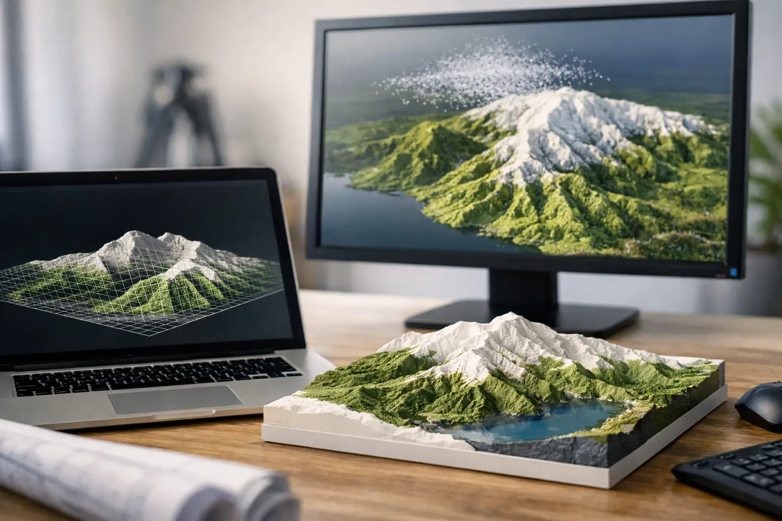
A Grasshopper terrain from elevation data is only as useful as the coordinate logic behind it. A visually convincing mesh can still be wrong by several metres, sit at the wrong datum, or become too heavy to support a workable Rhino file. For site analysis, grading studies, drainage checks and early massing, the aim is not simply to make a surface. It is to create an editable terrain model that stays traceable to real-world levels.
The most dependable workflow starts with a clean XYZ dataset, keeps a record of the source coordinate system, then creates a local modelling coordinate system inside Rhino and Grasshopper. This approach avoids GIS overhead while preserving the information needed to coordinate the terrain with survey, civil drawings and BIM models later in the project.
That's where Topo-grapher.com comes in, try it out for free
What the elevation file needs before it reaches Grasshopper
An XYZ file should contain three values per point: easting, northing and elevation. These may be supplied as a CSV, TXT or space-delimited file. Before building anything in Grasshopper, establish four details: the horizontal coordinate reference system, the linear units, the vertical datum, and the point spacing or resolution.
Horizontal coordinates tell you where the terrain sits on the earth. Vertical data tells you what the elevations mean. Both matter. A model using metres horizontally and feet vertically will look plausible at a glance but will produce unusable slopes. Likewise, applying an arbitrary vertical offset may be useful for presentation, but it must not replace the actual elevation values used for analysis.
Point density is the other practical decision. A dense LiDAR-derived dataset can reveal small banks, drainage swales and retaining edges, but importing every point into a design model may make Rhino and Grasshopper slow. A 0.5 m grid may be appropriate for a compact landscape intervention; a larger masterplan often needs a coarser spacing for early design. Use the density that supports the decision being made, not the greatest number of points available.
Building Grasshopper terrain from elevation data
1. Define a site area that matches the modelling task
Do not download a broad rectangle simply because the data is available. Include enough context to understand incoming roads, adjacent land, drainage routes and proposed connections, but keep the boundary purposeful. An excessive area increases point count, generation time and mesh complexity without necessarily improving the design decision.
For a building plot, include the full site plus a sensible perimeter beyond proposed works. For a flood route, public realm scheme or campus study, extend the area far enough to capture the upstream and downstream topography. The right boundary depends on whether you are testing local levels or wider landform behaviour.
Topo-grapher can generate an XYZ point-cloud file from a drawn boundary, coordinates or location search, giving Rhino and Grasshopper users a direct starting point without manually extracting and cleaning GIS elevation data.
2. Match Rhino units to the incoming dataset
Set the Rhino document units before creating geometry. If the exported coordinates and elevations are in metres, use metres. If the source is in US survey feet or international feet, confirm which one applies before scaling anything. Scaling after a terrain mesh has been built is possible, but it is an avoidable source of errors when the same model later receives building geometry, survey control or civil references.
Keep the source coordinate system in a panel within the Grasshopper definition, alongside the dataset date and point spacing. This small amount of documentation prevents a common coordination problem: a model is passed to another team member, but nobody can establish whether its elevations are local, projected or adjusted for visual purposes.
3. Move large map coordinates closer to the Rhino origin
Real-world eastings and northings can be large. Rhino can display them, but geometric operations and visual precision are generally more stable when the active terrain is close to the model origin.
Read the XYZ file with a `Read File` component, split each row into its three values, and convert those values to numbers. Before feeding them into `Construct Point`, subtract a chosen reference easting and northing from every X and Y value. Keep the elevation unchanged unless you deliberately need a local vertical zero.
For example, if the first or centre point is E 500,000 and N 180,000, store those values as `E0` and `N0`. Build points using X = E - E0, Y = N - N0 and Z = elevation. The terrain now sits near 0,0 in Rhino, while the translation values preserve its real-world location.
This is not a loss of coordinate accuracy. It is a controlled coordinate transformation. Record E0 and N0 clearly so the model can be repositioned or related back to project coordinates when needed.
4. Create a mesh, then control its boundary
Pass the local points into a `Delaunay Mesh` component to generate a triangulated terrain mesh. Delaunay triangulation is fast and useful for irregular point clouds, which makes it a sensible default for elevation data. However, it connects the outermost points as a convex hull. On an L-shaped or otherwise irregular site, it can create triangles across areas that do not belong to the project boundary.
Use a closed site boundary curve as part of the definition. Depending on the workflow, cull points outside the curve before triangulation, trim the resulting mesh, or remove faces whose centroids fall outside the boundary. The important point is to check the edge condition rather than assuming the imported point cloud defines the site correctly.
Inspect steep edges, watercourses, kerbs and embankments after meshing. Elevation points describe sampled ground, not every physical breakline. If a sharp retaining wall is critical to the proposal, confirm it with a survey, civil drawing or a separately modelled edge. A terrain surface should not imply a level of certainty that the source data cannot support.
5. Test the terrain before using it for design decisions
A terrain mesh should be checked in section, not only in perspective view. Use a series of section curves through known high and low areas, then compare the levels against source points or available survey information. Test several locations across the site, particularly at proposed entrances, accessible routes, building thresholds and drainage discharge points.
Grasshopper is especially useful here because the same point cloud can drive analysis without rebuilding the base terrain. Sample mesh elevations at proposed building corners, calculate gradients along paths, identify cut and fill tendencies, or colour the mesh by slope range. Keep the analysis geometry separate from the source mesh so design iterations do not overwrite the original terrain reference.
When calculating gradients, make sure the horizontal distance and vertical difference use matching units. A simple ratio can be converted into percentage grade, but its result is only meaningful if the terrain and proposed geometry share the same coordinate system and scale.
6. Keep the model light enough to revise
A highly detailed mesh is not automatically a better project model. Dense point clouds can slow down definitions, obstruct viewport work and make file sharing difficult. If the terrain is being used for early option testing, consider creating two versions: a lighter working mesh for everyday design and a denser verification mesh for critical level checks.
Decimation should be deliberate. Grid-based thinning retains a reasonably even distribution of points, while random reduction can leave gaps in small but important features. For a site with localised complexity, retain greater density around buildings, paths, drainage channels and proposed earthworks, then use a coarser sample across undisturbed areas.
Avoid converting a terrain mesh to an unnecessarily heavy NURBS surface. For most Grasshopper analysis and Rhino coordination tasks, a clean mesh is more stable and more honest about the nature of the source data. Use a surface only where a downstream operation genuinely requires one, and test whether smoothing has changed significant levels or slopes.
Coordinate discipline matters more than a smooth mesh
The strongest Grasshopper terrain definition makes its assumptions visible: source units, coordinate system, local origin, vertical reference, boundary and point spacing. These parameters should sit at the top of the definition, not disappear inside a cluster with no explanation.
That discipline pays off when the project moves from concept design to coordinated site work. A terrain model can then support fast design exploration without becoming an isolated visual object that has to be rebuilt when survey, civil engineering or BIM information arrives. Start with data you can trace, keep the transformation explicit, and let the terrain remain useful when the questions become more demanding.



