
Drainage Analysis Using Terrain Models in BIM
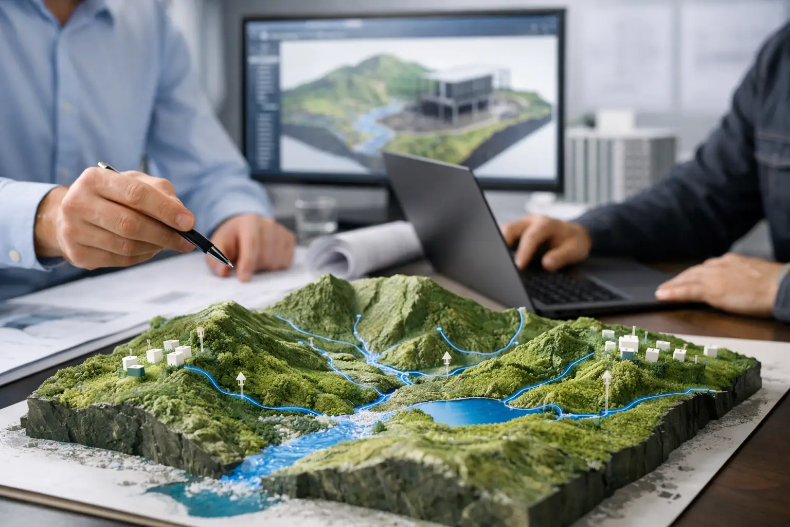
A terrain model can look convincing and still be useless for drainage decisions. If its points are too sparse, its coordinates are uncertain, or its elevations have been flattened during import, the model may hide the shallow low point that directs water towards a building entrance. Drainage analysis using terrain models starts with a simple requirement: use editable elevation data that retains real-world position and vertical variation.
For architects, landscape teams and BIM coordinators, this is not a substitute for a civil engineer’s drainage design. It is an early design-control exercise. It helps the project team see where water is likely to collect, where gradients are impractical, and where the proposed design risks fighting the existing landform before those issues become costly coordination work.
What a terrain model can tell you about drainage
A terrain model represents the ground as a set of surveyed or remotely captured elevation points. When those points are converted into a surface, each part of the site has a height and a slope. Water generally follows the steepest available descent, collecting in local depressions and travelling along natural swales, road edges, retaining-wall toes and constructed channels.
The useful output is not a colourful slope diagram alone. It is a set of design questions. Does runoff move away from the building perimeter? Is there a low point between the proposed access route and the façade? Will a level terrace create a basin against rising ground? Does a parking area need a defined fall towards gullies or a planted edge?
Existing terrain analysis is particularly valuable during feasibility and concept design, when a project may still have several massing, access and external-level options. A few metres of building movement can change the amount of cut and fill, alter overland flow paths and introduce a retaining requirement. Seeing that relationship early gives the team options that are difficult to recover once floor levels and grids are fixed.
Start with dependable existing-ground data
Drainage conclusions are only as credible as the terrain beneath them. A visual map, satellite image or manually traced contour drawing may help orientation, but it is not enough for decisions that depend on centimetres of fall. Start with source data that states its coordinate reference system, acquisition method and practical resolution.
LiDAR, official national mapping and photogrammetry datasets each have different strengths. LiDAR can capture fine changes across open ground, while mapped terrain products may be more consistent over a wider area. Photogrammetry can be useful where current surface context matters, but vegetation, parked vehicles and roof edges can distort the apparent ground. The appropriate source depends on the site, its cover and the decision being made.
Before modelling, check the horizontal and vertical coordinate systems. A model placed in an arbitrary local coordinate system can still appear correct internally, yet create problems when it is aligned with a civil survey, utility record or neighbouring package. Vertical datum differences are equally significant. A spot level from one dataset cannot be compared casually with a survey level from another if their datums differ.
For early analysis, obtain a boundary that extends beyond the plot. Water does not respect red lines. Include uphill land, adjacent roads, likely discharge routes and enough downstream context to identify the receiving low area. On a constrained urban site this may mean only a modest buffer. On a rural or sloping site, the relevant catchment can extend much further.
Build a model that remains workable in BIM
The terrain needs enough points to reveal meaningful breaks in slope, but not so many that the authoring model becomes slow and difficult to edit. This balance matters especially in Revit, where excessively dense Toposolids can affect file performance and make grading changes cumbersome.
A clean XYZ or CSV point file gives the team control over this trade-off. Import the points at the correct units and coordinates, then inspect the result before adding design geometry. In Revit, create or import the Toposolid and compare a selection of known levels against the source dataset. In Rhino or Grasshopper, construct a surface or mesh from the XYZ data, then check for long triangles crossing ridges, kerbs or drainage channels. In SketchUp and Archicad, use the equivalent terrain or Mesh workflow, keeping the original point file available for traceability.
Do not assume that a smooth-looking surface is accurate. Interpolation can bridge across a ditch, wall, culvert inlet or abrupt embankment, producing an attractive but misleading plane. Add breaklines, targeted points or separate surfaces where the site contains features that control runoff. A kerb line, for example, can be more influential than a broad area of mild slope.
Topo-grapher is useful at this stage because it produces editable, real-world-coordinate XYZ terrain data for BIM and modelling workflows, rather than a static terrain view. The aim is to get dependable ground data into the model without turning an architectural site study into a GIS exercise.
Test flow direction before designing drainage elements
Once existing ground is in the model, begin with simple checks. Review the site in plan with contour labels, then use section cuts through the building, access and likely drainage paths. A 3D perspective is helpful for communication, but sections and spot elevations reveal whether a gradient is actually achievable.
Identify high points, low points and constrained edges
Mark local high points and depressions around the proposed building footprint. Pay close attention to thresholds, ramp bases, basement access, loading areas and changes between hard landscape and planting. These are places where modest grading changes can create ponding.
Boundary conditions matter as much as internal levels. A site may fall naturally towards a neighbouring property, a public highway or a protected landscape edge where discharge is restricted. Conversely, an existing road may direct surface water into the site during intense rainfall. The terrain model exposes the geometry, but local drainage strategy and approvals determine what can be done with it.
Measure gradients, not just elevations
A level difference means little without the available run. A 300 mm fall over 30 metres is gentle; the same fall over three metres is steep and may be unsuitable for accessible routes, paving systems or maintenance access. Measure gradients along actual flow paths, not only perpendicular to contours.
For external works, distinguish between surface falls that shed water and gradients that remain usable. A terrace may need a subtle fall away from the building, while a planted swale may need enough longitudinal fall to avoid stagnant water without eroding the soil. The correct values depend on the surface material, drainage detail, climate, accessibility requirements and local standards.
Compare existing and proposed ground
The most useful drainage review occurs when existing and proposed surfaces are visible together. Proposed grading should direct water intentionally: away from façades, across paving towards collection points, into planted attenuation areas or towards an approved connection. It should not merely smooth the model around the building.
Use cut-and-fill comparisons to identify where grading has become excessive. A design that solves local drainage by raising one corner of a site may create a retaining issue, obstruct an access route or send runoff towards another constraint. Iterating the building finished-floor level, hardscape levels and landscape form together is usually more effective than treating them as separate packages.
Know what terrain analysis cannot prove
Terrain-based analysis shows likely overland flow and topographic risk. It does not calculate pipe capacity, infiltration rate, groundwater behaviour, sewer surcharge, flood return periods or the performance of a drainage network during a storm. Those require survey information, ground investigation, rainfall data and specialist hydraulic or hydrological analysis.
It also cannot compensate for poor source data. Dense LiDAR may still miss a recently altered site, and a coarse national terrain dataset may not resolve small features such as thresholds or channels. Where levels are critical to consent, construction setting-out or flood assessment, commission an appropriate topographic survey and coordinate it with the model.
The practical value lies in using terrain data early enough to influence design. A clean model makes it easier to ask the right questions: where will water go, what has changed, and can this level strategy be built without creating the next problem? That is a better starting point for civil coordination than discovering a trapped low point after the external works package is already underway.



