
DEM versus DTM for Accurate BIM Terrain Models
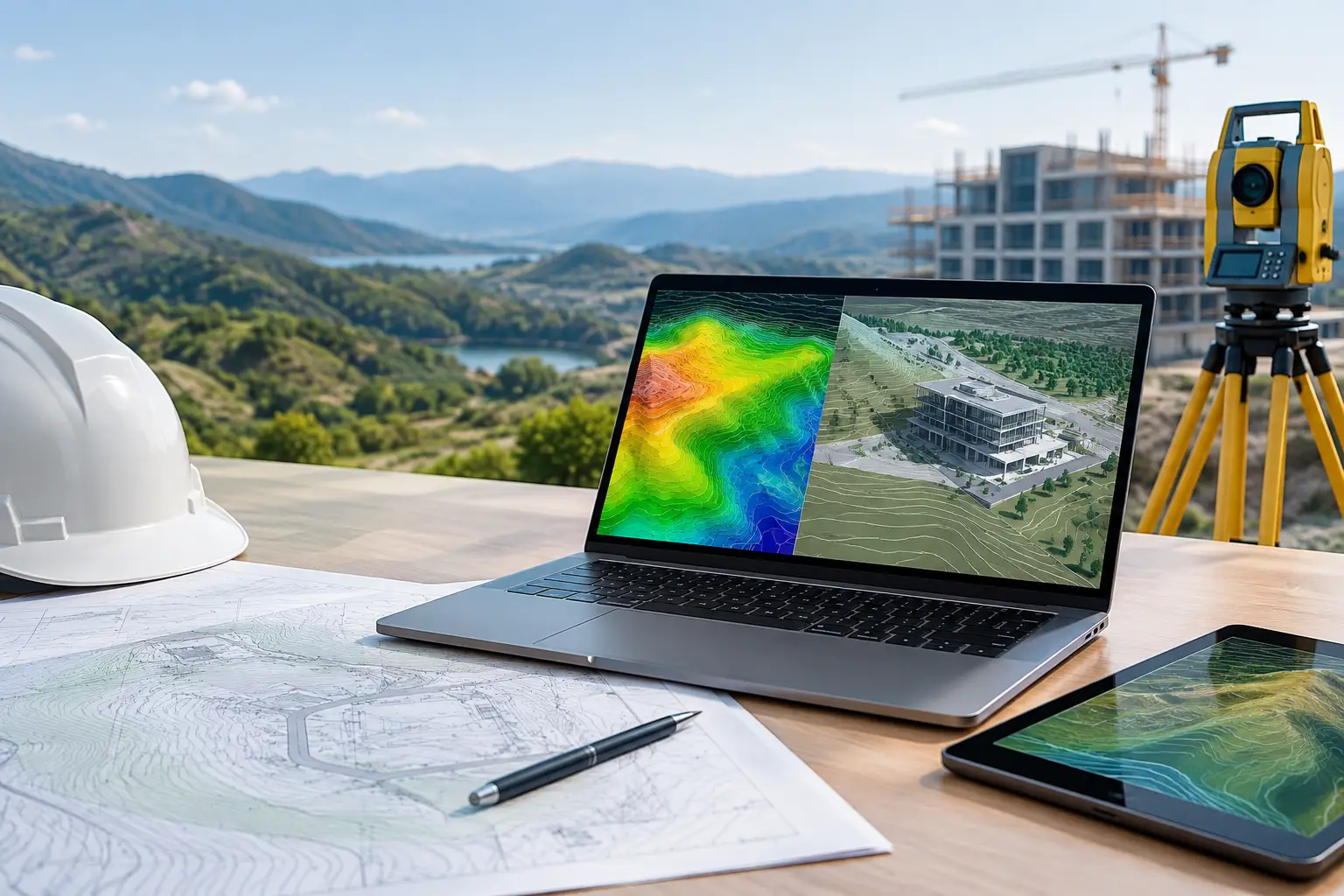
A site model can look convincing and still be wrong where it matters. If a proposed access road appears to cut cleanly into a hill, but the source surface includes trees, walls or building roofs, the model can mislead decisions on levels, drainage and excavation. That is the practical issue behind DEM versus DTM: both describe elevation data, but they do not always represent the same physical surface.
For architects and BIM teams, the useful question is not which acronym is more correct. It is whether the data represents bare earth at a resolution and coordinate reference suitable for the decisions you need to make.
DEM versus DTM: the working distinction
A Digital Elevation Model, or DEM, is a broad term for a digital representation of elevation. It may describe the ground surface, but it can also refer to elevation captured from a surface containing features above the ground. Its exact meaning depends on the data provider, country and production method.
A Digital Terrain Model, or DTM, normally means a bare-earth model. Vegetation, buildings and other surface objects have been removed or classified out, leaving the terrain that supports grading, drainage studies, retaining-wall design and building level coordination.
The terminology is not consistent enough to use labels alone as a specification. Some mapping agencies use DEM as their standard name for bare-earth elevation data. Others use DTM for a terrain surface derived from LiDAR. In practice, check the dataset description, source method, point spacing, vertical accuracy and whether above-ground features have been filtered.
A third term often enters the discussion: Digital Surface Model, or DSM. A DSM records the uppermost visible surface. In a wooded area, that means canopy; in an urban block, it may mean roofs, parapets, bridges and street furniture. A DSM can be valuable for visual context, solar analysis or height studies, but it is not normally the right source for a proposed finished-ground model.
Why bare-earth data changes design decisions
Terrain modelling is often treated as an early-stage visual task. It becomes a technical task as soon as the model informs a finished floor level, accessible route, cut-and-fill assumption or drainage direction.
Consider a sloping plot with mature trees along one boundary. A surface dataset captured from imagery may rise with the canopy, producing a false ridge several metres above actual ground. If that surface is imported directly into Revit, SketchUp or Rhino, it can make the site look steeper than it is. A proposed path might appear non-compliant, or a building platform may be set unnecessarily high.
Buildings create a similar problem. Surface elevation around adjacent properties can include roof geometry rather than the land below it. This distorts contours, hides local depressions and can create abrupt terrain spikes that look like survey errors inside a BIM model.
A bare-earth DTM is generally the better starting point when you need to understand existing levels. It supports an editable representation of the land rather than a visual shell draped over whatever was visible from the sensor.
That does not mean a DTM is automatically suitable for every project. A national terrain dataset may be excellent for feasibility work across a large site but too coarse for setting out a small threshold, channel drain or retaining-wall footing. Source quality and project stage still govern the decision.
Read the data specification before you model
Before generating terrain, establish what each published figure actually means. Resolution, point spacing and accuracy are related, but they are not interchangeable.
Point spacing describes how far apart elevation observations are sampled. A one-metre grid may provide enough definition for broad landform and early massing. A higher-density LiDAR-derived point cloud can show ditches, banks, kerbs and smaller changes in grade more clearly. Yet dense data can also create unnecessarily heavy terrain elements if every point is imported into a BIM authoring model.
Vertical accuracy describes confidence in the elevation value itself. It matters when comparing proposed levels with existing ground, especially on shallow gradients. A site falling only 300 mm across a courtyard needs more scrutiny than a site dropping several metres across the same distance.
Also confirm the coordinate reference system and vertical datum. Horizontal coordinates may be in a national grid, a projected coordinate system or geographic latitude and longitude. Elevations may be relative to an orthometric datum, a local benchmark or ellipsoidal height. Mixing these without a defined transformation can put the terrain in the wrong place or create a persistent vertical offset.
For project coordination, record the source date as well. Even a high-quality DTM cannot show a recently formed embankment, demolished structure or regraded car park. Existing terrain data is a useful design input, not a replacement for a project-specific topographical survey where construction tolerances require one.
Choose the right terrain source for the task
For early feasibility, masterplanning and site massing, an official terrain dataset is often the right balance of speed, coverage and usable accuracy. It lets the team test building position, road connections, accessible gradients and likely earthworks before commissioning more detailed survey work.
For landscape concept design, a DTM is particularly useful because planting zones, swales, paths and terraces respond to actual ground form. It gives the landscape architect a base surface that can be reshaped deliberately, rather than one that carries accidental canopy or roof geometry.
For detailed grading, drainage design and construction documentation, use the available terrain model with appropriate caution. Survey control, utility information, design levels and civil engineering requirements take priority. The BIM terrain should be coordinated with those inputs, not treated as a final authority simply because it has a high point count.
A DSM has a different role. Use it when the height of trees or neighbouring buildings matters to the study. Keep it separate from the bare-earth terrain so the distinction remains clear to everyone reviewing the model.
A practical route from elevation data to BIM
The most reliable workflow is to generate only the area required, validate it before import, then keep model density proportionate to the job.
First, define the site boundary with enough margin for approach roads, drainage routes and relevant surrounding slopes. A model cropped exactly to the building footprint often produces misleading edge conditions. Include the land that controls how water and access move towards the scheme.
Next, select a source identified as bare earth where ground modelling is the aim. Review its metadata for capture date, resolution, vertical reference and known limitations. If the project is in an area with woodland, dense urban fabric or complex coastal conditions, inspect the resulting points and contours carefully before treating the output as a design base.
Then export an XYZ or CSV point file in real-world coordinates. This gives you editable terrain data rather than a fixed web image. Topo-grapher is designed for this step: define the site area, generate terrain from available official mapping, LiDAR or photogrammetry sources, and download a clean point dataset for the modelling environment.
In Revit, bring the points into a Toposolid workflow and avoid importing more points than the element needs. Excessive point density can slow regeneration and make editing difficult, while adding little value to a building-scale model. In Rhino or Grasshopper, retain the denser source where analysis requires it, then create a simplified working surface for general design use. In SketchUp and Archicad, check that triangulation follows the expected ridges and drainage paths rather than bridging across critical breaks in slope.
Finally, perform a quick plausibility check. Compare the terrain against mapping, known spot levels, road edges and visible contour behaviour. Look for spikes around structures, flat patches where the site should fall, and implausible drainage directions. These are often signs of surface objects, sparse sampling or a coordinate issue rather than genuine terrain.
Do not let the acronym make the decision
DEM and DTM are useful labels, but neither replaces a review of what the data contains. For BIM terrain, a bare-earth surface with known source quality, correct coordinates and manageable point density is normally more valuable than a visually detailed model of the wrong surface.
Treat terrain as a project input that becomes more precise as the project develops. Start with dependable real-world ground data, model only the resolution your current decisions require, and make the handover to survey and civil coordination explicit when the design moves towards construction.



