
BIM GIS Terrain for Editable Site Models
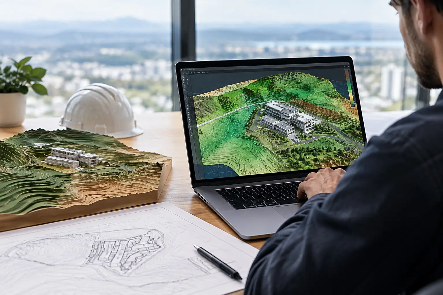
A site model can look convincing while being technically unhelpful. A textured map or web terrain viewer may show slopes and contours, but it will not necessarily give a Revit user editable points, a reliable datum, or coordinates that align with the civil engineer’s information. BIM GIS terrain addresses that gap by turning authoritative elevation data into geometry that can be used, checked and revised inside the design model.
For architects and landscape teams, the value is not simply seeing the site in 3D. It is being able to test finished floor levels, retaining walls, accessible routes, drainage falls and cut-and-fill implications against real-world ground conditions before the model becomes difficult to change.
Why BIM GIS terrain is different from a visual terrain model
GIS and BIM serve different jobs. GIS manages location-based information across an area: elevation, parcels, imagery, flood zones, roads and survey layers. BIM manages the designed asset: floors, walls, toposolids, levels, grading elements and coordinated building geometry. A useful site workflow needs both, but it should not require every project architect to become a GIS specialist.
The practical output of a BIM GIS terrain workflow is an editable dataset, usually XYZ points. Each row contains an easting or X coordinate, a northing or Y coordinate, and an elevation or Z value. Import those points into the modelling environment and they become the basis for a terrain surface that remains tied to real coordinates rather than an approximate hand-built mesh.
That distinction matters when decisions carry a vertical consequence. A 300 mm change to a platform level can alter step counts, ramp lengths, drainage routes and the apparent height of the building from the street. If the underlying terrain is only visual reference material, those decisions are being tested against an unreliable base.
Authoritative data does not remove the need for a measured survey. It does, however, provide a defensible starting model for feasibility, planning studies, landscape concepts and early coordination. The correct level of detail depends on project stage, terrain complexity and the resolution of the available source data.
Build BIM GIS terrain from a defined boundary
The first technical decision is the area you request. Do not generate a broad square simply because it is easy to draw. The boundary should include the building footprint, expected grading zone, access routes, drainage paths and enough surrounding land to understand the site’s approach and runoff direction.
For a compact urban plot, include the pavement, kerb line and neighbouring ground where level changes influence entrances or boundary conditions. For a rural or landscape site, extend far enough uphill and downhill to read catchment behaviour and natural landform. A terrain clipped too closely to the building often hides the very gradients that should inform the design.
1. Select the coordinate reference system first
Coordinate mistakes are more disruptive than most modelling teams expect. If a terrain uses one coordinate reference system and a survey, building model or civil drawing uses another, elements may arrive displaced, rotated or at the wrong elevation. A site can also appear correct visually while its values are referenced to the wrong vertical datum.
Before exporting points, establish the coordinate system expected by the project. This should match the project survey where one is available. Record whether elevations are orthometric heights, which relate to mean sea level, or ellipsoidal heights, which derive from satellite positioning. The difference can be significant enough to invalidate level comparisons.
In early design, teams sometimes work with a local coordinate system to keep geometry close to the model origin. That can be sensible, particularly in Revit, but it must be a deliberate transformation. Keep the original real-world coordinates documented so the model can be reconciled with survey and civil information later.
2. Use point spacing that suits the decision
More points do not automatically create a better BIM model. Dense LiDAR-derived terrain can contain hundreds of thousands of points across a modest site. That density may be appropriate for analysis in GIS, yet it can make a Revit toposolid slow to generate, difficult to edit and cumbersome in a shared central model.
Choose point spacing according to the site and the question being asked. A relatively open development parcel may work well with a coarser, evenly distributed point set for massing and initial levels. A steep embankment, drainage channel, coastal edge or complex existing landscape may need closer spacing to retain meaningful breaks in slope.
Retain critical terrain features even where the overall dataset is simplified. Ridge lines, ditches, retaining edges, road crowns, swales and changes in paving level often matter more than a uniform increase in point density. A good terrain export represents the shape that affects design decisions, not every available measurement.
3. Check the source and its limitations
Elevation data may be derived from national mapping programmes, LiDAR or photogrammetry. These are useful sources, but they do not all represent the same thing. A digital terrain model aims to show bare earth, whereas a digital surface model can include trees, buildings and other objects above ground.
That distinction is especially relevant on wooded sites. A surface generated from canopy returns can make a slope appear higher or more irregular than the ground beneath it. Likewise, older datasets may predate roadworks, demolition, regrading or new flood defences.
Review the source date, stated resolution and vertical accuracy before treating the output as design control. For construction setting-out, detailed grading or legal boundary work, obtain a current site survey. BIM GIS terrain is strongest when it accelerates early work and helps the team ask better survey questions, rather than replacing survey deliverables beyond their intended use.
Export data that your modelling software can use
CSV or plain XYZ is generally the most direct terrain exchange format because it is simple, inspectable and supported by many design applications. Open the file before import. Confirm the delimiter, column order, coordinate units and decimal format. A file using commas both as decimal separators and column separators can fail silently or produce distorted geometry.
For Revit, a manageable XYZ point set can be used to create a Toposolid. Keep the imported terrain separate from proposed grading where possible. That allows the existing ground to remain as a reference while pads, subregions or design surfaces are tested against it. If the model is heavy, reduce point density before import rather than trying to repair performance after the terrain is embedded in multiple views.
SketchUp users can use XYZ data to create a terrain mesh, then inspect it with sections and shadow studies. The key check is scale: confirm that metres, millimetres and feet have not been confused during import. A terrain that is 1,000 times too large is usually a unit issue, not a data issue.
In Archicad, the same coordinates can inform a Mesh workflow. In Rhino and Grasshopper, XYZ points can be turned into points, interpolated surfaces or triangulated meshes depending on the required control. For computational workflows, preserve the raw dataset and generate a simplified working version separately. This keeps the process reproducible when the site boundary or point spacing changes.
DXF point exports can be useful where the civil team needs CAD-based reference, while IFC may assist broader coordination workflows. Neither format automatically guarantees coordinate compatibility. The receiving team still needs to know the reference system, units, elevation datum and any local offset applied to the model.
Verify terrain before design decisions depend on it
A short validation pass prevents avoidable errors. Compare several terrain elevations against known spot levels, a survey drawing or publicly available contours. Check the highest and lowest points, then inspect the direction of major slopes. If a road visibly falls towards a junction but the model rises, stop and investigate before placing levels.
Also review the terrain in section rather than relying on perspective views. Sections quickly reveal stepped triangulation, spikes, missing data and excessive smoothing. Use them to test practical conditions: can an accessible route achieve the required gradient, where does water naturally move, and does the proposed finished floor level create an unrealistic retaining condition?
When sharing the model, state what the terrain represents. Label it as existing ground from a specified dataset and date, distinguish it from surveyed information, and note its intended design stage. This is simple coordination hygiene, but it prevents an early feasibility model being mistaken for final grading information.
Keep the workflow fast enough to use early
The strongest argument for BIM GIS terrain is speed with traceability. The team should be able to define the site, generate points, bring them into the chosen modelling tool and begin checking levels without manual contour tracing or a separate GIS production exercise.
Topo-grapher is designed for that task: define a boundary on a map or by coordinates, generate terrain from available mapping data, then download an editable XYZ dataset for the BIM workflow. The output is useful because it enters the software where design choices are already being made, rather than remaining a static web view.
Treat the first terrain model as a working instrument. Use it early, compare it with incoming survey information, and refine it as the design gains certainty. That approach gives the project team a clearer ground condition at the point when changing the building is still relatively inexpensive.



